Introduction
So you want to take your QRO radio out into the field and run a full 100 watts RF power to gain some S-units on the receiving end (compared to running a QRP rig).
To do so you need a DC power source that can provide you with approximately 20A DC current at a solid 12.8 volts.
In the past, to meet this power requirement, you either needed to stay in or near your vehicle, or carry a very large capacity lead acid battery.
Nowadays (since 2018) there is a battery chemistry that is safe to use and allows for rapid draws of energy from very small packs. That chemistry is LiFePO4.
In this guide, we'll cover the basics of selecting appropriate LiFePO4 cells, how to build a pack and share some thoughts on how to get the most out of your pack.
Document Revision History
Original version of this document: Feb 3, 2019.
Last update: Feb 19, 2023 - removed old links that no longer work, minor clarifications and removal of CALB CA180 cell comparisons.
Warning
Batteries can be dangerous. Please exercise caution when building your pack. The LiFePO4 cells referenced below can discharge very large amounts of energy quickly, almost like large capacitors. Use caution whenever you handle your pack, triple check your wiring, fuse where possible, yada, yada, yada. You are responsible for your own project. Cross check the information outlined below as you will be responsible for what you decide to implement.
The Cells
First, don't confuse LiFePO4 with LiPo or other "Lithium" chemistry cells. Dig deep into the vendor's specs for the cells until you find the true chemical make-up. This guide only applies to LiFePO4 cells with a nominal voltage of 3.2V DC per cell.
You will need 4 cells in series (4S) to create a nominal 12.8 volt pack. But how big a cell do you need? To determine that, we need to do a bit of math.
First, estimate how you will use the radio you plan to power with this pack. Will you be 25% transmit and 75% listen (a runner), or 5% transmit and 95% listen (a search and pouncer)?
Next, decide on how long you will want to be able to operate for without a recharge. We are assuming a solar panel and suitable charge controller are not in the picture for your portable use.
And finally, determine how much energy your radio draws on both RX and TX (for the power level you plan to use). It might be a good idea to go with a worst case scenario for power draw and just assume the maximum your radio will consume on it's highest RF power setting. So, for the TX, use the manufacturer's specification for your radio. For the RX, (optionally hook up a dummy load to the antenna connector so you don't accidentally transmit with no antenna attached and) use a DC power meter to monitor how many amps your radio draws while listening.
Let's use a popular QRO portable radio, the Yaesu FT-891, in this sizing example. Here are it's specifications:
RX amp draw: 1.1A (with button backlighting turned down as low as possible)
TX amp draw: 10.45A (at 40 watt SSB output - 1 S unit better than 10 watt phone QRP and usually gets the job done (in year 2023 HF condx).
Use pattern: 25/75 (a runner for POTA activations)
Use duration: 2 hours
So, that's 1.1A x 0.75 (75% of the time) x 2h = 1.65Ah required for RX. And then 10.45A x 0.25 (25% of the time) x 2h = 5.225Ah required for TX.
Add up the RX and TX Ah requirements and we have 6.875Ah required.
Now, with the old lead acid cells, (if running at the stated 20h consumption rate or less) you could use approximately 50% of the battery's rated capacity. With LiFePO4, at any consumption rate not exceeding 2C (2 x the rated capacity of the pack), you can use approximately 70-80% of the rated capacity. For this example we'll go with 70%.
So, we take the required 6.875Ah and divide by the 0.7 usable capacity and determine that I need a 9.82 Ah LiFePO4 pack. We'll round up to 10Ah. So, 4 x 10A 3.2V nominal LiFePO4 cells need to be acquired.
There are many LiFePO4 cells on the market, but since 2019 HAMs have been reporting good results with Headway brand cells. These cylindrical cells come in capacities such as 8Ah, 10Ah, 12Ah and 15Ah. I bought 4 of the Headway model 38120S 10A cells:

The BMS
A BMS, or Battery Management System, is an electronic means of protecting the pack from overcharge, overcurrent and the dreaded over-discharge. Depending on the BMS model, it may also protect from charging your pack at less than 0 degrees Celsius. Also, depending on the model, it may perform top balancing of your cells when the cells are being charged (more on that later). Modern BMSes are FET based and require very little power to operate.
Now, let's back up a bit and take a moment to outline some key/core attributes of the LiFePO4 battery technology:
- Overcharge decreases the capacity of the cells.
- Overcurrent (charge or discharge) simply isn't safe.
- Charging at a temperature of less than 0 degrees Celsius will greatly impact the capacity of the cells. You never want to do this.
- Overdischarge just once KILLS your cells immediately. You NEVER want to do this.
Now let's look at the manufacturer's specs for the 10A Headway cells I've selected for my portable pack build:
1C maximum charge current, 0.3C - 0.5C suggested charge current
1C - 5C maximum constant discharge current, 10C maximum burst discharge current
3.65V maximum charge voltage, 3.8V maximum cell voltage
2.0V minimum cell voltage
0-45 degrees Celsius for charging
-20-65 degrees Celsius for discharging
So, for the portable pack build, I've selected this BMS:

It's relevant specs are as follows:
allows up to 10A charge current
allows up to 120A discharge current
allows up to 3.75V maximum cell voltage
allows down to 2.1V minimum cell voltage
optional temperature-based control
self consumption less than 30uA normal, less than 20uA when over discharged
I will be fusing both the positive and negative leads with 25A fuses so overcurrent protection isn't actually that important here. I also don't care too much about the charge current limit as I'll be using a charger where I set the charge current limit to 0.2C (2 A for a 10 Ah pack). But otherwise, the protections fit the spec of the Headway cells.
In regards to cold temperature charge protection, we can accommodate by simply never charging our pack when it's cold. Winter Field Day outdoor operators may choose to ensure their battery packs are kept warm next to their bodies. If you want to charge LiFePO4, I highly recommend the cells be at least 5 degrees Celcius.
I have seen some other LiFePO4 cells on the market whose specifications suggest no less than 2.5 V per cell, so I might suggest not relying on the BMS for over-discharge protection. I would not want to get anywhere near 2.1V. In fact, I would never want to go much below 3.0V per cell, ever. So I will be adding a LVD (low voltage disconnect device) to catch an under-voltage situation very early.
The LVD
The low voltage disconnect device is my personal safety to ensure that if I'm operating at 100 watts RF output and my pack is low in remaining capacity, the pack will disconnect the DC load well before the cells are drawn down to dangerously low voltage levels.
LiFePO4 voltage over time goes something like this: each cell starts off fully charged with a resting voltage of around 3.4V per cell. Soon that drops to somewhere between 3.3V and 3.2V and that's where the cell voltage levels stay for the majority of the time. Then there's a lower knee where all of a sudden voltage drops down to 3.0V per cell and then you know you're pretty much empty. Further discharge of the pack will quickly pull the cells down into the 2.xV range where you can risk destroying the cells.
With all protection devices, they draw energy to keep you safe. So, you need a device that draws as little energy as possible so that you can "play radio" for as long as possible.
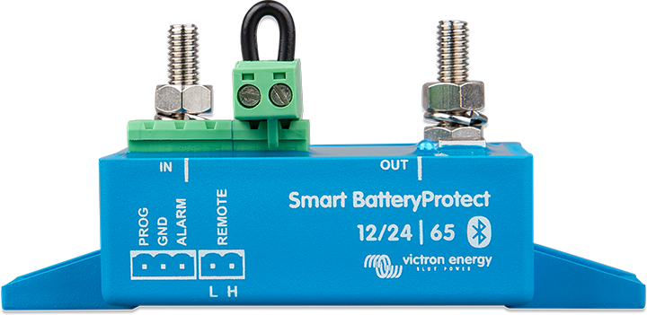
For my LVD, I've chosen Victron Energy's Smart Battery Protect 65. There's also a classic Battery Protect 65 without bluetooth, but the amp draw (when in use) of the new Smart model is less than that of the older classic (with the bluetooth turned off after you've set your protection parameters).
With the Smart version, I pay for the additional protection it provides with 1.2mA of additional current draw. I set the low voltage disconnect at 12V (3V per cell) and enjoy the disconnect delay of 90 seconds.
I have also installed a buzzer so that I can be alarmed when a disconnection is imminent. When it starts beeping, I have 90 seconds to finish the QSO and power down.
The DC Power Analyzer
Like every good HAM, I like to see stats for my DC power draws. I enjoy seeing how many amps I've drawn from the pack, my current amp draw, as well as my lowest pack voltage so far. This gives me some indication as to where I am in regards to pack capacity remaining and also helps me learn about my DC system.
There are many DC power anaylzers on the market but I recommend you look for one that looks like the below (as it has been quite reliable and informative):

Now it is important to note that the DC power analyzer that I use requires 50mA to operate, so like all other safety and monitoring devices, consider the cost of it's service. I think, however, it is very worthwhile to use. If the analyzer indicates you've got lots of power left when you need one more contact to activate a park, turn up your radio's power to maximum and reach for that distant station. If, on the other hand, if the analyzer indicates that you are near exhaustion of your pack's usable capacity, perhaps turn your radio's RF output power down, or disconnect other devices that you may be powering from the pack in order to hold out a little bit longer for that last contact or to finish up with a pile-up.
Optional but Recommended: Bottom Balancing (Just Once)
Cells, even from the same lot/batch, may have differing capacities. Without going into massive detail on the topic, I'll just state that when cells have different capacities, their voltages will drift away from each other either at top (charged) or bottom (discharged) charge levels.
I am a big fan of only charging my LiFePO4 packs to 90%. If we recall key attribute 1 of LiFePO4: overcharge reduces capacity. Now, if I'm only going to 90% charge level, do I care if my cells have slightly different voltages at 90% full? No.
Now when I take the pack down to the bottom, if one of my cells is a little lower in capacity than the rest, it may show a significantly lower voltage than the other cells. If I take a cell below 2.5V I worry about it, not to mention the 2.0V minimum outlined by Headway. Ideally, when my LVD cuts me off at 12V, each of my cells will be at exactly 3.0V - all nicely out of the 2.xV range with zero risk to any cell.
Hitting that LVD voltage is going to be common for me... as I know I'll be trying to get just one more contact required to make the POTA activation valid and I will likely not be carrying a solar panel and charge controller with me (to limit weight).
So, I want to bottom balance my cells. To do this, I'm going to place a load on each cell individually until the cell reaches 2.8V. With these 10A cells, I'm going to start with a 2A load to bring the voltage down to 2.8V and then immediately remove the load. Then once the voltage bounces back up, I'll put a 0.5A load on the cell taking it down to 2.8V again and immediately remove the load. Finally, once it bounces up again I'll do one more draw at 0.5A to 2.8V and then remove the load to get a final resting voltage just under 3.0V for each cell. This is just below my LVD set point of 12V or 3.0V per cell. So, now, when my LVD kicks in, all cells will be balanced at 3.0V.
Once bottom balanced, I'll assemble the pack in 4S configuration and charge to 90%. I won't let my BMS do any top balancing, otherwise my bottom balance will be messed up. On the more elaborate BMSes, you can turn balancing off. On the basic BMS I've chosen for this build, I know balancing doesn't start until 3.6V per cell. But as I only plan to charge to 90% anyways, I will charge at a much lower voltage of 3.45V per cell. More on charging later.
So, what's an easy, no-risk way to discharge cells at exact amp rates with load disconnects immediately when the bottom voltage is reached? Use a battery workstation from the Remote Control world. I personally use a Revolectrix Cellpro Powerlab 8 v2 (no longer available as of 2022 but there are many similar options available at your local RC shop). This device is a bit of overkill if you don't normally build LiFePO4 packs, but it is flawless at disconnecting the load when the low voltage is reached. It also provides a metering of energy removed from the cell which allows for capacity testing on both the cell and pack levels.

For discharge work, the massive power supply really just powers the Powerlab 8's fans (as the load is a big resistor (making heat) built into the Powerlab 8 unit). I hook up a cell and select a discharge-only program. I set the discharge rate and the low voltage to stop at. It works flawlessly and beeps at me when done. All I have to do is keep swapping cells and kicking off the discharge program.
Here is a table of what I observed in the bottom balancing process for my Headway 38120S 10Ah LiFePO4 cells that all had the same date of manufacture:
| Cell | StartV | Rate | mAh | Dur | StartV | Rate | mAh | Dur. | StartV | Rate | mAh | Dur | EndV | TotalCap |
| 1 | 3.342 | 2A | 9916 | 5:00 | 3.214 |
0.5A |
769 | 1:32 | 2.943 | 0.5A | 86 | 0:10 | 2.884 | 10771 mAh |
| 2 | 3.342 | 2A | 9753 | 4:52 | 3.218 |
0.5A |
1073 | 2:08 | 2.991 | 0.5A | 122 | 0:14 | 2.908 | 10948 mAh |
| 3 | 3.342 | 2A | 9544 | 4:46 | 3.216 |
0.5A |
904 | 1:48 | 2.998 | 0.5A | 146 | 0:19 | 2.915 | 10594 mAh |
| 4 | 3.342 | 2A | 9717 | 4:51 | 3.215 |
0.5A |
856 | 1:42 | 2.986 | 0.5A | 100 | 0:13 | 2.901 | 10673 mAh |
StartV is the start voltage at the begin of each controlled discharge. Rate is the rate of the controlled discharge. The mAh column shows the amount of energy drawn from each cell for the discharge run. The Dur column indicates how long the controlled discharge took (in hours and minutes). All draws are down to a stop voltage of 2.8V. The EndV column indicates the final resting voltage of each cell after the 3 discharge runs. The TotalCap mAh column is calculated by summing up the total mAh drawn out of each cell.
What's also interesting is that the total measured capacity of each cell is not equal. Some carry less energy than others. So again, it's important to treat the pack with the weakest cell in mind. Nice to see though that all cells deliver at least 10Ah.
Now, one thought: the final resting voltages are not exactly the same, they are +/- 0.015 volts. You could connect all of the cells in parallel for a couple of weeks and let them balance even further, but to me, a difference of 0.030V between the lowest and highest cells is close enough. When we do some controlled cycle testing later, we'll measure the cell voltages at the top of the charge and at the bottom of the discharge and see how close they are then. But what we really care about is that no one cell goes much lower than the other cells at the bottom - we want them all to hit the safe 3.0V level at the same time.
The Pack
As this is a DIY build, we'll need a way to keep the 4 cells held together. We could just strap them together with duct tape and zip ties, but there are more elegant ways. In this example, I use Headway's own cell holders that can be joined together to make different cell pack arrangements.

With a 4S pack, the common arrangements are 4x1 and 2x2. I am going to try a 2x2 arrangement for this build.
4x1:
2x2:


Once the pack is assembled, I will protect everything with heat-shrink PVC. This will hold everything together and keep the wires all neat. I'll use a clear PVC so that the pack can be inspected and I can show other HAMs my handiwork. As the heat-shrink PVC I'm using is 5 mil thick, I'll use a couple of sheets to really create a robust wrap for the cells, similar to that of an RC car's battery pack.

The Cell Interconnects
The cells in the pack need to be linked in series. While one could make linkages out of ring connectors and wire, bus bars are a better option. Bus bars also help hold the pack together. Some folks will flatten copper pipes and drill holes for the cell bolts to go through... or purchase bus bars from the manufacturer of the cells. In this example I will take the easy route and acquire bus bars from Headway as they are perfectly sized for the Headway cells.

The Wiring and Connectors
We will utilize 12 gauge wire for the common and output portions of the build, and 14 gauge wire for the charge input. The BMS cell monitor wires are delivered with the BMS so their gauge has already been chosen. All wire is stranded copper with good temperature-rated insulation.

For the connections to the loads and charger, we'll use Anderson PowerPole connectors, the 45A crimp versions. To clearly differentiate the charge input from the load output, we'll use a yellow colored Anderson PowerPole vs the usual red colored one for DC positive. Yes, this does not follow the original standard for PowerPole colorings, but I like to think the charge input is like the sun (as since 2020 I've exclusively charged this pack with solar power). The colors I have chosen do match the ARES/RACES guidelines and I assemble my ends in the ARES/RACES orientation. Here's a great guide on PowerPole connector assembly with the ARES/RACES orientation.

In selecting the wire sizes for minimal voltage drop for both the max 5A charge input and max 20A load output, I like to use this chart compliments of Blue Sea Systems Inc.
I'll add that I usually use marine grade wire as well, with all strands of the copper tinned to prevent oxidization and the highest temperature rating wire insulation.
What I don't do, although many do recommend it, is both crimp and solder all connections. I'm more of a crimp-only guy. Here's why:
- all of my ring-terminal connectors do utilize an adhesive heat shrink that keeps moisture out of the crimp as well as provide strain relief for the crimp
- I use an appropriate crimper for each type of connector that ensures a perfect crimp
- all of my wire is marine grade with tinned copper strands to ensure that the copper does not oxidize
- I prefer flexible connections over rigid (soldered) connections that can potentially crack in the rigours of portable use
Assembly
The best guide I can share on pack assembly is Julian OH8STN's pack assembly video. Julian has built a number of DIY packs and does a fantastic job of outlining the detail of each step of the build. In this video he builds a pack very similar to mine, but with a different BMS and a 4x1 cell arrangement. Julian's video was the inspiration for my build.
Weight
Weighing the pack, it comes in at 1587g / 3.5 lbs:

Charging
LiFePO4 needs a CC/CV charge algorithm. This differs from the bulk/absorb/float model used for lead acid batteries. You never want to float a LiFePO4 pack.
The CC or constant current part of the charge cycle is first. Energy is pushed into the pack at a fixed amp rate until the pack voltage comes up to the desired charge voltage.
It is suggested to charge LiFePO4 cells as slowly as possible for best longevity. Headway recommends 0.3C - 0.5C charge rate, effectively a 3A - 5A rate for this 10A pack. I try to charge my Headway 10Ah pack at 0.2C, effectively a 2.0A rate to ensure super long cell life and maximize on my investment.
The CV or constant voltage part of the charge cycle is next. The charger reduces charge current to keep the voltage of the pack right at the set charging voltage. Once the current reduces to C/20, the charge can be considered done and the battery full.
Your charger must be LiFePO4 compatible with a CC/CV charge algorithm. It should not pulse or do anything "smart" for desulphation of lead acid batteries. I highly recommend you turn the charger's pack voltage down to a maximum of 13.8V (4S cell voltage down to 3.45V) and charge rate down to 0.2C with a bottom balanced pack and enjoy extended pack longevity.
Ensure that the charger you choose turns off completely when the charge rate in the CV stage reduces to the equivalent of C/20 A. Again, you don't want to float a LiFePO4 pack.
Capacity Testing
With the cells bottom balanced, the pack assembled and charged CC/CV at 2A to 13.8V, it's now time to do some pack capacity testing. Normally, you'd just use your DC power analyzer and see this information in the field, however, since I have a Powerlab 8 that can dissipate up to 100W of power internally (or 1433 watts of power into an attached lead acid battery), we might as well do it on the workbench.

For the first test, let's use a 2A discharge rate. This would represent a QRO radio like the FT-891 operating casually at low power levels.
For the test we'll omit the LVD and DC power analyzer. Just the pack with BMS overhead will be tested.
We'll then charge the pack back up and repeat the test with a higher discharge rate of 4A, representing a QRO radio running at mid power.
We'll have the Powerlab 8 stop the discharge at 12.0 volts for both tests, just like the LVD would do in the field.
Here are the results and observations:
| When | Pack | Cell 1 | Cell 2 | Cell 3 | Cell 4 | Observation |
| Top of first charge CC/CV at 2A/13.8V, just off the charger (power supply). | 13.74V | 3.386V | 3.382V | 3.508V | 3.409V |
Cell 3 is slightly into the upper knee earlier than the others indicating that this is the weakest/lowest capacity of our cells. |
| 1 hour after the first (2A rate) discharge to 12.0V. | 12.84V | 3.210V | 3.210V | 3.210V | 3.210V | Cells have bounced back up to approx 3.2V per cell after being drawn down to 3.0V per cell in the test. All cells in perfect balance at the bottom of the cycle. Discharge at 2A to 12.0V gives 9817mAh usable capacity. |
| Top of second charge CC at 2A/13.8V, 10m off the charger (Powerlab 8) | 13.38V | 3.348V | 3.349V | 3.350V | 3.349V | The Powerlab 8 does a CC charge and then stops... no CV portion (until I figure out how to program it to do so). However, the charge did put in 8607mAh. So perhaps this is a "even friendlier" charge protocol. Unfortunately I could not check the individual cell levels right when it finished... but once settled, they are pretty well balanced with only 0.01V difference between them. |
| 30 minutes after the second (4A rate) discharge to 12.0V. | 12.84V | 3.210V | 3.210V | 3.210V | 3.210V |
Cells have bounced back quickly to approx 3.2V per cell after bring drawn down to 3.0V per cell in the test. |
So I think we can sum up the results as follows:
- With LiFePO4 you get the mAh out that you put in, no matter what discharge rate (no Peukert effect and very high cell efficiency).
- Charging CC/CV at 2A/13.8V will take the cells to nearly full. Any higher charge voltage and capacity of the weakest cell in the pack may begin to reduce due to top imbalance. For long pack life, don't charge past this point.
- Charging CC at 2A to 13.8V appears to be the ideal. The cells are still in good balance at the top of the charge. Given the charge and discharge test stats, this charge protocol puts in approx 81% of the capacity. If we take it that the cells are about 90% full when the charge stops, we're cycling in the performance tests between 90% and 10%. We actually might want to stop a little earlier at 12.2V instead of 12.0V so that we can cycle between 90% and 20%.
- Given that the cells are in balance at the top (with the CC at 2A to 13.8V charge protocol) and at the bottom (when discharged to 12.0V), I lean towards running the pack between 90% and 10% with the usable capacity of approximately 8600mAh. This will give me around 2 hours of heavy radio use and a lot more if taking it easy.
Build Cost Breakdown
Like many cost-conscious HAMs, you might want to compare what it cost for this DIY build (in 2019) against some similar-capacity store-bought offerings.
LiFePO4 cells, busbars and plastic holders + shipping = $141.43 CAD
BMS + shipping = $9.39 CAD
Shrink wrap + shipping = ~$5 CAD (estimated cost as I already had the shrink wrap purchased in bulk)
Electrical connectors, fuses, wire bits, PowerPole ends, etc. = ~$30 (estimate cost as I already had these items as leftovers from other projects)
The cost adds up to approximately $185 CAD with fusing and PowerPole connectors installed for both charging and load output. However, to compare to a basic store-bought battery (without all of the extras) we're at approximately $155 CAD.
The price of the optional LVD will vary depending on which one you get. The one shown above (Victron Smart Battery Protect 65) was approximately $90 CAD, shipped.
The price of the optional DC power analyzer will vary depending on which one you get. The one shown above was $20 CAD, shipped.
The Future - Solar
Sometimes I want to take the pack on a trip and operate for longer than 2-8 hours. For example, the ARRL Field Day event each summer. To keep operating I will need a solar panel and charge controller.
For solar panel, there are many options. I have tried the following 2.
I have one of PowerFilm's R14 rollable panels. With both IP67 and MIL-STD-810G standards met, this is a robust, waterproof panel that can take a bit of a beating. Sized approximately 15" x 42", this panel delivers a maximum of 0.9A of charge current via my Genasun charge controller (outlined below).

I also have a 45 watt standard glass/aluminum-framed panel. While big and heavy, it does the job very well. There's something to be said about classic glass panels - they usually perform to their ratings (even up in Canada where we are much further from the equator).
For charge controller, we know that we need one specifically for LiFePO4 batteries, so something that uses a CC/CV charge algorithm and that will not float the battery. Given the observations above in regards to max pack charge voltage, especially with CC/CV, the controller must charge at no higher than 13.8V. The charge controller can be either MPPT or PWM, but MPPT would be preferred for efficiency as we're trying to squeeze out as much power from the limited panel size and light conditions as possible. We also want RF quietness from the charge controller - how annoying would it be to be making your own QRM while trying to operate?
I can only find one suitable option for charge controller: the Genasun GV-5 for LiFePO4 MPPT charge controller with a custom configuration for CV voltage level. Note: to order a custom voltage, click Buy Now from the Genasun website and then configure and add a custom controller to your cart. Also note: this MPPT charge controller has a load output with an LVD included but it's only good for 5A - fine for a QRP rig but not our example FT-891 QRO setup. I would also suggest specifying the LVD disconnect voltage as 12.0V and the reconnect voltage as 12.2V so that if you do place a small load on this output (like a USB charge port to charge your phone), it will ensure your LiFePO4 battery pack never goes below 12.0V.

In testing so far with the 45-watt rated classic panel and the Genasun GV-5, I see the full 45 watts of power being put into the battery pack when the sun is shining. The GV-5 pulls all possible power out of the panel... and at this charge rate of approximately 3A, I can run any radio all day long and finish the day with a full battery pack that supports my activities well into the evening.
Questions or Comments?
If you have any questions or comments about this guide, please do not hesitate to contact the author at